In our previous post, we defined stray currents, where they come from and some effects they can have on grounding and other systems with the capacity to carry current, intentionally or not.
Like many other types of protection systems, prevention is the best option when it comes to stray current control. When they cannot be prevented, multiple options exist for solving the issues related to stray current without the use of an impressed current system.
In this post, we examine 3 design practices and solutions to controlling stray currents.
1. Lowering the resistance of the return path, i.e. providing a preferred path
As stray currents can increase from a circuit to a nearby structure in proportion to the voltage potential at a given point in the circuit, an effective means of reducing stray currents is to reduce the resistance within the return circuit. In the case of DC Rail traction systems, this may involve increasing the level of cross rail bonding, or providing additional low resistance conductors (i.e. large cross section area copper conductors) bonded along the rail to reduce the return path resistance.
2. Improving the Isolation of the return path from nearby structure
An obvious means to reduce stray currents involves increasing the isolation of the electrical circuit from surrounding structures. Again in the example of DC Rail traction systems, this means physically isolating the rail from the structures that support them and isolating other metallic structures such as overhead support masts, fences and platforms. This can prove difficult to achieve in practice as the potential leakage points can be numerous and not obvious. For example through concrete to support masts from overhead wiring or through the track supports to fencing, etc.
3. Providing shielding or collection systems
An effective and widely used method of stray current control is to provide an interconnected system of bonding designed to collect stray currents and return the current directly back to the source. This method, effectively used in conjunction with the above two design methods can be quite effective in collecting any remaining stray currents and conducting back to the source without corrosion “exit points.” The design philosophy is to collect all stray currents (recall that collection points are not a point of corrosion) and conduct back to the source without the current transitioning to other structures.
This can be achieved most effectively in practice for example on DC rail traction systems that are fully supported by concrete structures whereby the reinforced steel can be made continuous and act as a path to collect the stray currents and conduct directly back to the source. This should also be supplemented by a continuous bonding conductor designed to be a reference for bonding all metallic nearby structures thereby avoiding stray currents through the elimination of potentials between the collection system and these structures.
Shown below are installation photos showing such a collection system, common bonding conductor, and earth bridges, which are an effective way to bond to the steel within concrete structures to avoid corrosion within the structure-reinforced steel.
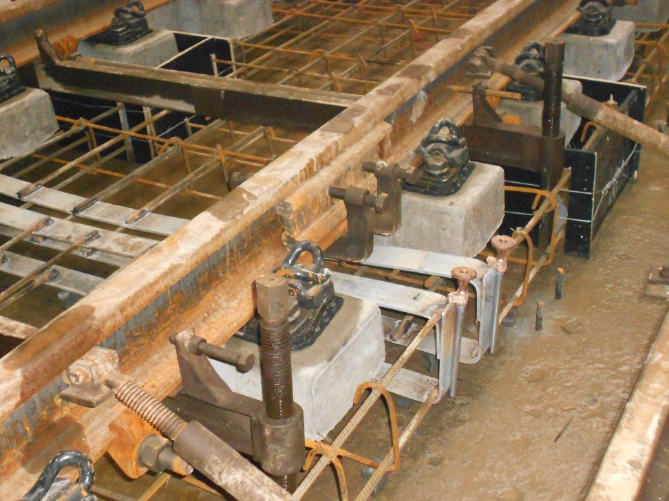
Before Concrete Pour
Stray current collection system (before concrete pour), located under the rail, showing all rebar continuously bonded for effective collection of stray currents. Two earth bridges are shown on the right, which will later be used as bonding points to ensure continuity between the expansion joint for the structure.
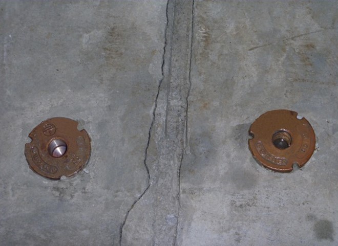
After Concrete Pour
Below are the two earth bridges shown after the concrete pour, before the bonding jumper is installed. The bonding jumper will ensure a continuous path of the collection system back to the source when installed.
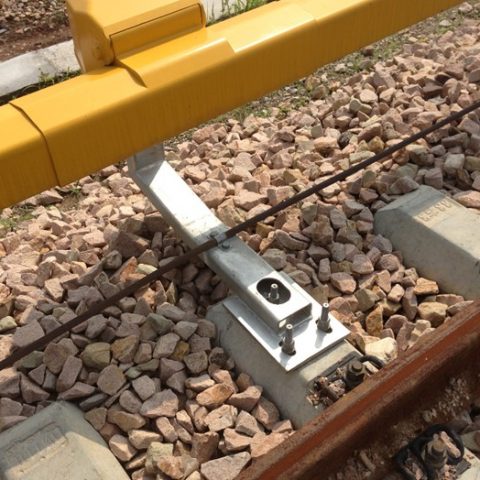
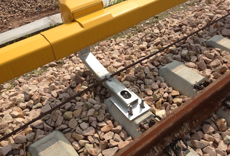
Final Installations
Common Bonding Conductor shown running trackside for the purpose of bonding to the same potential all nearly metallic structures thereby avoiding voltage potentials between structures and subsequent stray current to and from the collection system.
For common bonding conductors, the balance between material cost, performance and service life proved to be a significant challenge. This led us to introduce the nVent ERICO Cu-Bond Round Conductor, an innovative ground conductor alternative that overcomes the limitations of conventional materials.
To read more about how this conductor has been used in railway installation as a grounding and bonding conductor, read our post here.
Learn More About Comprehensive Electrical Protection
Stay on top of new trends, advice and information by subscribing to the nVent ERICO blog. Our electrical engineering and product experts regularly publish new information, and curate top resources with posts like this one.